|

Mixing of Sediment-laden Buoyant Jets
Introduction
→Sediment-laden turbulent buoyant jets are commonly found in natural and engineered environments. Examples include volcanic eruptions, deep sea hydrothermal vents, discharge of partially-treated wastewater and dredging operations. The settling of particles from a sediment buoyant jet depends on the complex interaction of particles with turbulent fluctuations and the mean flow - in particular particle re-entrainment due to the external irrotational flow induced by the jet (Fig. 1). The prediction of the fate and transport of sediment particles in buoyant jets is a problem of general scientific and engineering interest.
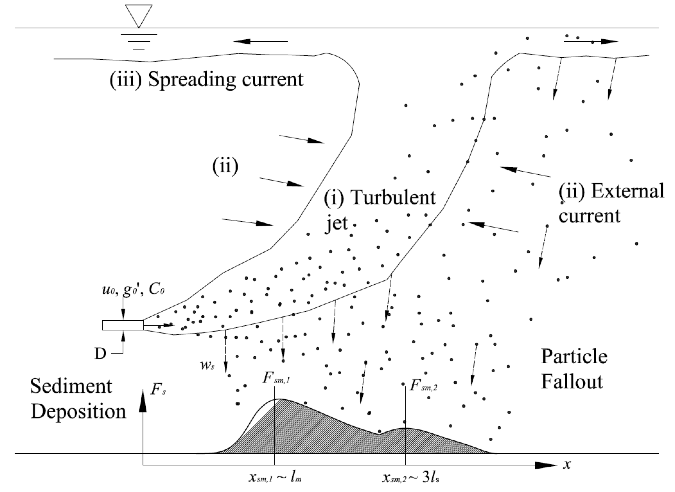
Figure 1. A schematic diagram of a horizontal sediment-laden buoyant jet.
3D stochastic particle tracking model
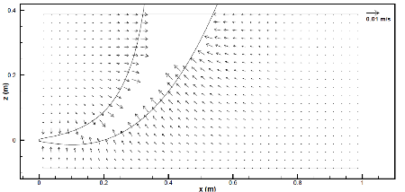
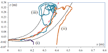
We proposed a three-dimensional (3D) stochastic particle tracking model to predict the sedimentation from an arbitrarily inclined sediment-laden buoyant jet in a stagnant ambient. The simple model predicts the entire 3D jet flow field via a coupling of semi-analytical models for the mean flow as well as turbulent fluctuations. The mean flow for the turbulent buoyant jet is determined using well-validated integral model JETLAG/VISJET, while the external jet-induced irrotational flow field is computed by a distribution of point sinks along the jet trajectory (Lai and Lee 2012, Fig.2a), and the surface spreading current by an integral model validated with computational fluid dynamics (CFD) simulations. Turbulent velocity fluctuations are modelled by a Lagrangian particle velocity autocorrelation function which mimics the trapping and loitering of sediment particles in turbulent eddies. The turbulent fluctuations are stochastically generated from a self-similar profile of the turbulent kinetic energy derived from CFD solution of jets and plumes. Particles are numerically tracked in the unsteady flow field using the equation of particle motion from the jet nozzle till their final deposited position (Fig.2b).
(a) |
(b) |
Figure 2. (a) The jet-induced external flow field of a horizontal buoyant jet on particle velocity and (b) its influence on the complex particle trajectories.
Experiments
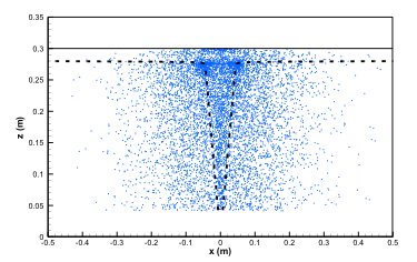
We carried out extensive laboratory experiments of horizontal sediment-laden buoyant jets to study the deposition and mixing of sediment particles in buoyant jet flows (typical experimental image shown in Fig. 3). The experiments were carried out in a 1m × 1m × 0.45m deep water tank with a horizontal 6mm diameter nozzle located in the middle of the tank wall and 15cm above the tank bottom. Steady jet flow (with different buoyancy by mixing tap water with ethanol) was supplied from an over-head tank. The sediment particles were fed to the jet flow at a constant rate using an hourglass. Sediment bottom deposition profiles were measured using a collection tray and cross-sectional sediment concentrations were measured using particle imaging. A total of 36 experiments on horizontal sediment momentum jets and 33 experiments on sediment-laden horizontal buoyant jets were performed, covering a wide range of initial jet velocity (0.29-0.88m/s), jet densimetric Froude number Fr = 9.8-28.3, particle diameters (115-716μm) and densities (1.16-2.65g/cm3).
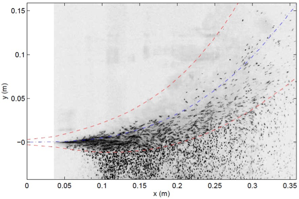
Figure 3. Experimental image of a horizontal sediment-laden jet at its centerline plane. The dash-dot line is the jet centerline trajectory and the dash lines are the jet top-hat boundaries, predicted by JETLAG.
Result
Horizontal sediment buoyant jet
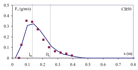
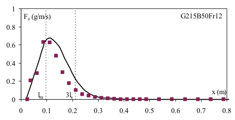
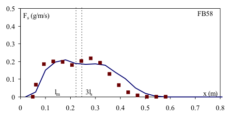
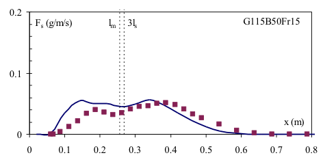
Model predictions compare well with measured sediment deposition profiles which are transversely lumped into a 1D profile. For the experiments using coarse particles (Fig. 4a,b), most particles fall out from the jet region, forming a single-peak deposition profile. For the experiments using fine particles (Fig. 4c,d), a substantial portion of sediment is transported to the surface spreading current by the rising plume flow forming double peak deposition structure.
The 2D particle deposition patterns reveal that there is a narrow zone of high particle density close to the jet nozzle for coarse sand particles (Fig.5a). The transverse extent of the deposited sediment increases with distance downstream. For the fine sediment experiment (Fig.5b), a circular cloud of deposited sediment can be observed near the location when the buoyant jet curves sharply upwards - reflecting the sediment fall out from the rising plume and spreading layer.
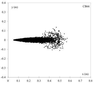
(a) u0 = 0.65m/s, Fr = 19.5
deq = 166μm, ws = 1.95cm/s
|
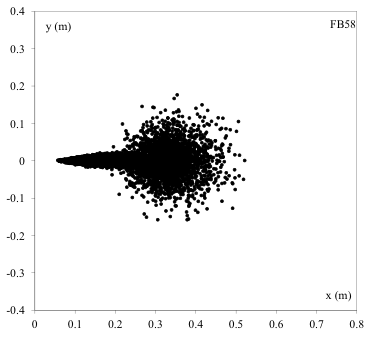
(b) u0 = 0.61m/s, Fr = 14.5
deq = 133μm, ws = 1.36cm/s |
Figure 5. Predicted 2D deposition profiles (particle position) for horizontal sediment buoyant jet.
Vertical sediment buoyant jet
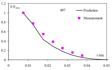
The vertical sediment-laden buoyant jet is an analog for volcanic eruptions and seabed hydrothermal vents. Particles are transported by the jet flow upwards; fall-out is observed near the jet edge and from the spreading current. Due to jet-induced entrainment, the falling particles are attracted towards the jet and follow a curved trajectory, forming a sediment veil surrounding the jet. Sediment deposited as a circular mound around the source, resembling the formation of a volcano. The comparison between predicted and measured deposition profiles (Ernst et al, 1996 and Sparks et al, 1991) is very good (Fig.6).
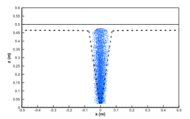
(a) D = 4mm, u0 = 0.75m/s, Fr = 34.2,
d = 275μm, ρp = 3.21 g/cm3,
ws = 4.3 cm/s, C0 = 0.75g/L
|
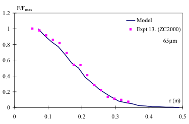
(b) D = 7mm, u0 = 0.35m/s, Fr = 10,
d = 65μm, ρp = 2.47 g/cm3,
ws = 3.3 cm/s, C0 = 0.35g/L
|
Figure 6. Predicted sediment distribution in water (left), and radial sediment deposition distribution and comparison with data (right) for two cases.
Key Publications
- Chan, S. N. and Lee, J. H. W. (2015). A particle tracking model for sedimentation from buoyant jets. Journal of Hydraulic Engineering, ASCE, (accepted for publication).
- Chan, S. N., Lee, K. W. Y. and Lee, J. H. W. (2014). Numerical modelling of horizontal sediment-laden jets. Environmental Fluid Mechanics, 14(1), 173-200.
- Lee, K. W. Y., Li, A. C. Y. and Lee, J. H. W. (2013). "Structure of a horizontal sediment-laden momentum jet." Journal of Hydraulic Engineering, ASCE, 139(2), 124-140.

  
|