Line Diffuser in a Cross Current
In coastal cities, partially treated wastewater is often discharged into the adjacent receiving water using submarine multi-port diffusers. The individual round buoyant plumes from the diffuser merge to form a “line plume” with finite length in a cross flow. The mixing of a line source of buoyancy of finite length in a crossflow can be modelled via a dynamic coupling of the near field JETLAG/VISJET model and a far field shallow water circulation model. The DESA method enables realistic three-dimensional (3D) environmental impact prediction from the near field around the sewage outfall to the far field sensitive receivers.
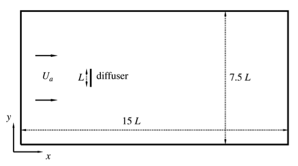
Figure 1. Experimental setup for a finite line plume in a perpendicular cross flow (L = 0.61 m).
Roberts (1979) performed experiments of a slot diffuser discharging in a steady current to study the mixing of a finite "line plume" in a cross flow (Fig. 1). The experiments show that the near-field dilution is governed by a cross flow Froude number, F = Ua3/b, where Ua = current speed and b = discharge buoyancy flux per unit length, representing the ratio of ambient velocity to buoyancy-induced velocity. Small values of F indicate a buoyancy-dominated flow, resulting in the formation of a buoyant surface wedge with an initial width greater than the diffuser length. On the other hand, high values of F represent a flow dominated by the ambient current.
To simulate the experiments with DESA, a 23 × 17 × 20 model grid is employed with open boundaries at two ends, with a horizontal grid size of 43.5 cm by 30.5 cm and 20 uniform vertical layers. The finite line plume is represented by a number (n = 4 - 6 for the present case) of equivalent noninterfering round plumes by preserving the same volume, momentum, and buoyancy fluxes per unit diffuser length. The videos below show the spreading of the wastewater field under different cross flow conditions.
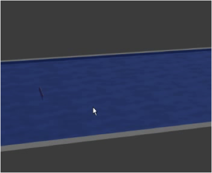
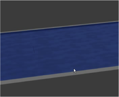
Video: Simulation of the line plume in perpendicular crossflow by DESA.
The DESA predictions agree well with the experiments of Roberts (1979) (Fig. 2):
- For F ~ 0.1, the mixed effluent has a plume-like pattern, with a surface buoyant layer and significant lateral spread. The surface width at the diffuser is larger than the diffuser length; both the extent of the upstream intrusion and the lateral width are well supported by the observations;
- As F increases, the surface buoyant layer is swept downstream; the lower surface concentrations for F ≥ 1 indicates bottom attachment of the effluent field; and
- For F ~ 10, the flow is advection-dominated and the lateral spread of the surface field is very limited.
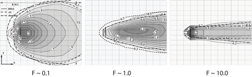
Figure 2. Computed surface tracer concentration field (in units of 0.01C0) and observed surface field for a finite line plume in a perpendicular cross flow.
As shown in Fig 3, the predicted dilution by DESA (Choi and Lee 2007) also agrees well with the asymptotic dilution equation (best fit of data) given by Roberts (1979).
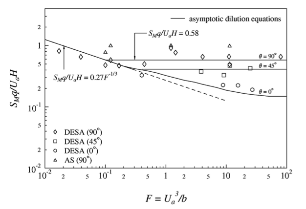
Figure 3. Computed minimum surface dilution (SM) as a function of cross flow Froude number F. Best fit of experimental data shown as asymptotic dilution equation (solid lines).
Publication
- Choi, K.W. and Lee, J.H.W., (2007), "Distributed entrainment sink approach for modelling mixing and transport in the intermediate field", Journal of Hydraulic Engineering, ASCE, Vol. 133, No. 7, pp. 804-815.